Features:
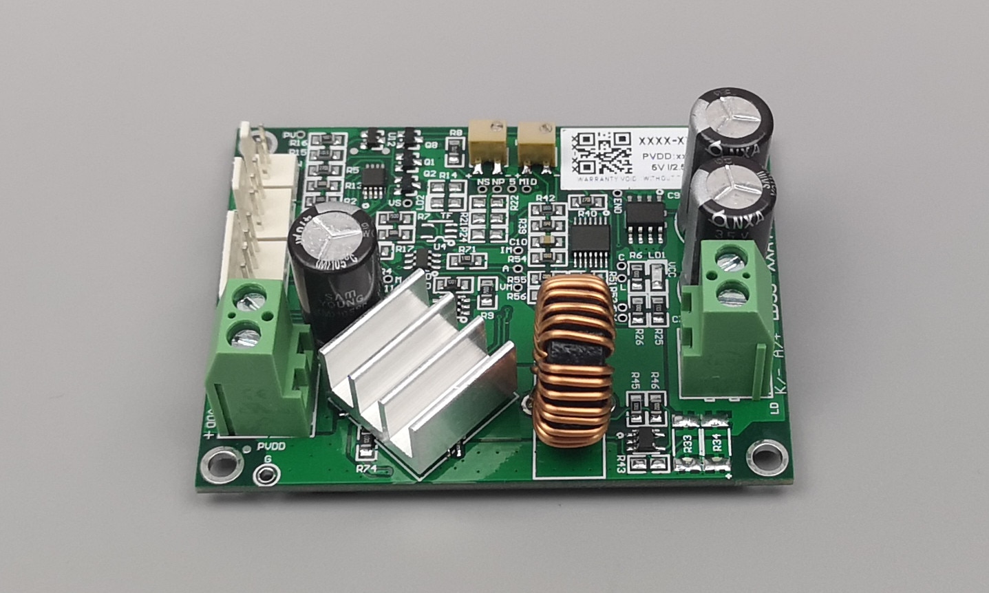
It is suitable for driving high voltage and low current laser diodes. Suitable for end pump side pump laser, semiconductor, welding, fiber and other lasers.
Perfect voltage adaptability, from a single tube to close to the supply voltage!
It is suitable for semiconductor laser test, LED light-emitting diode, various diode test, etc.
High speed, adaptive load voltage!
Ultra-high efficiency, without any additional heat dissipation measures for customers.
Single board design, small size, high reliability!
With internal and external control, that is, two analog inputs, one of which can be connected to a potentiometer
High-speed analog switches are used for internal and external control switching, which can be directly used for modulation. One analog is the working current and the other is set as the threshold current.
technical parameter:
Model: LDDH-xxA-MA
The highest adaptable voltage: 24V.
Power supply voltage: 12V/15V/24V/27V
Rated output current: specified by the user, up to 5A
Size: 70mm*54mm, height 25mm (board 20mm, thickness 1.5mm)
Current rise/fall speed: 1ms
Examples of applicable products:
NLIGHT, OCLARO, BWT..
Interface definition
1. PVDD power input port /5.0mm terminal block
Note: The voltage of PVDD must be at least 1V higher than the highest voltage of the load.
2. AN2/POT, the second channel analog input terminal, which can be connected to a potentiometer, or an analog quantity /2510-3P socket
3. CHSW channel (internal and external control) selection/2510-2P socket, if not connected, the analog input of CTL interface will be used by default
4. CTL control terminal/2510-6P socket
5. LD output port /5.0mm terminal block
A: Connect the positive pole of the load LD
K: Connect the negative pole of the load LD
Different application configurations
1. For applications that only need one analog quantity to directly control the output current of the drive board, at this time, only the CTL interface can be used to control the drive board, and no signal is connected to the AN2/POT and CHSW interfaces.

2 For applications that require internal and external control control, such as a power box, both local signals and external analog signal input ports are required. The local signal is generally provided by a potentiometer or generated by a local single-chip microcomputer, while the external control signal is provided by the user of the cabinet. At this time, Ic of CTL can be used to connect external analog signal, AN2/POT can be directly connected to a 10k (1k-100k is fine) potentiometer, or the local analog signal generated by Ic2 microcontroller, and then use CHSW SW to switch internal control and external control. can.

3 For applications that require fast modulation current (such as the power switch of a fiber laser), you can use the Ic of CTL to input the operating current signal, the Ic2 of AN2/POT to input the threshold current signal, and then directly use the TTL signal to output the SW of CHSW to modulate the current. Of course, it is also possible to directly modulate the analog quantity, that is, only use the analog quantity whose Ic input changes rapidly.
Note that when modulating, it is generally not adjusted between 0A and working current, but the threshold to working current. 0A is not good for the laser diode first, because there is no maintained threshold current, the thermal shock will be greater, which is not good for the laser diode. Secondly, the debugging performance is also very poor, which will not only lengthen the current rise time, but also generate excess response time, thereby reducing the modulation speed.


