Description
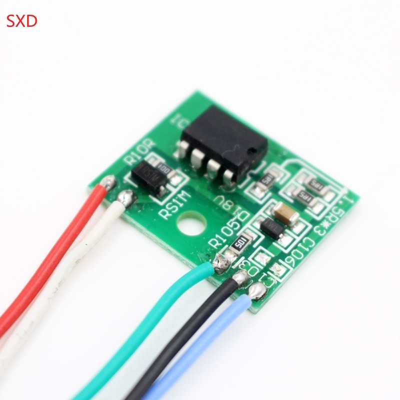
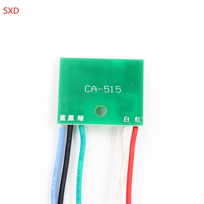
CA-515 (shared within 36W)
This series of modules is designed for repairing the secondary power supply damage repair of LCD LCD TVs and monitors. The maximum power can be up to 36W. It is easy for all colleagues to repair the LCD power supply. This series has small size, simple installation and basic implementation. Fully intelligent, high added value and other advantages, is a major change in the maintenance of LCD LCD TV power supply in the maintenance market, welcome to use!
*Installation Notes:
(1) After detecting that the +300V DC voltage is normal, confirm that the switching transformer and the secondary peripheral components are normal, and then confirm that the load has no short-circuit fault and then proceed to the following operation. .
(2) First remove the MOS tube or thick film IC on the original machine, and fasten the module to the heat sink, then fix it on the heat sink with a screw lock (the lock screw can’t be pressed too tightly, otherwise the module will be damaged).
(3) According to the figure, disconnect the fork in the actual circuit, and connect the color lines of the module as shown in the figure. It must not be connected incorrectly. After repeated verification, the switch will not be connected. ! Module leads cannot be extended under unnecessary conditions. Otherwise it will affect normal operation.
* Description of each lead connection:
1. Red line: Connect the main voltage +300V through the switching voltage device (ie, the D-pole of the MOS transistor, the thick-film IC D pole).
2. Black line: Connect the negative pole, that is, the power tube is hot.
3, blue line: Connect the original machine main voltage (3.3V or 5V) regulator optocoupler 4 feet (some original multi-optocoupler in parallel according to the original machine connection), 3 feet grounding.
4, white line:. Connect the original machine switch transformer feedback coil rectifier diode (pictured).
5. Green line: Connect the original main voltage +300V
