Description
Description:
The drive performance of these non-L298 motor driver chip can be compared, the driver focus on current and efficiency, effectively motor power and battery life. Can withstand high current overload, the maximum current up to 30A.
This drive also has a brake function can be quickly stopped the motor, brake quickly, braking obvious, easy to implement this feature
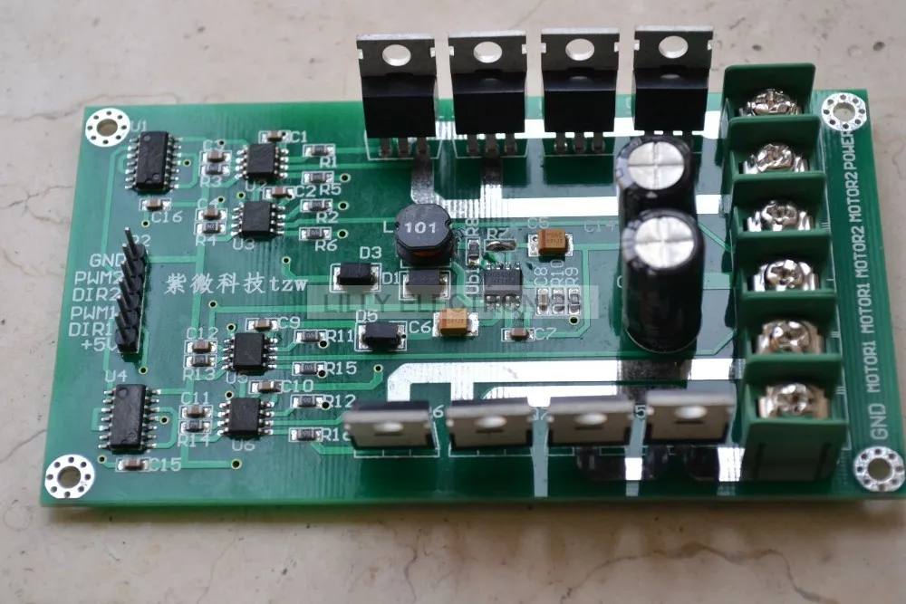
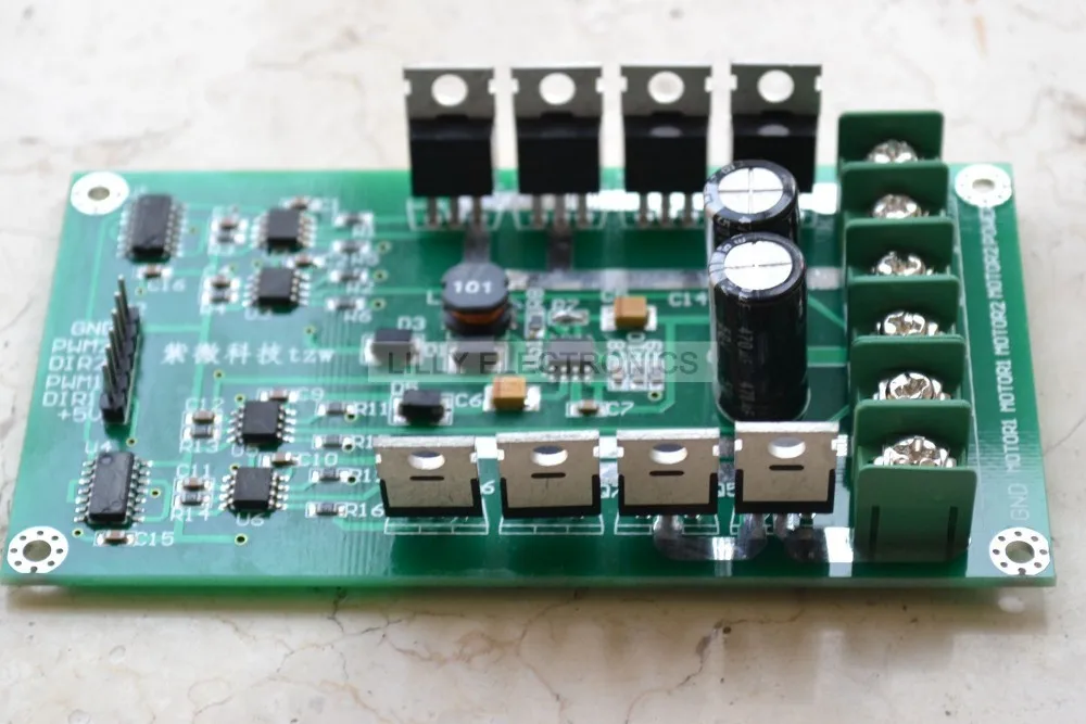
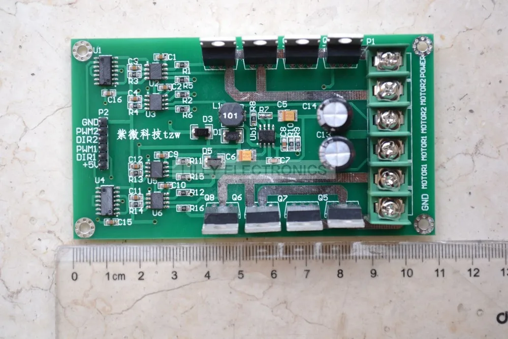
The drive uses the full two half-bridge driver chip + low resistance N-channel MOSFET components. Complete two half-bridge driver chip reliable drive mode, the MOSFET switching losses to a minimum. Improve power utilization. MOSFET driver chip comes with hardware brake function and power feedback.
This drive is superior integrated low power chip solution and the other half-bridge power margin in the coordinated combination of programs and complex issues and complementary drive problems
N-channel MOSFET IRF3205 MOSFET, use two dedicated half-bridge driver chip on the top tube using the bootstrap capacitor, so that the tube has enough drive voltage of the MOSFET channel can be opened quickly, improve motor acceleration curvature, but also quickly for the motor brake. This allows the trolley can quickly start can quickly kill the car.
The driver can operate at 0% -99% of the duty cycle of the PWM modulation, the motor driving voltage can be obtained sufficiently.
Features:
Motor forward: DIR = 1 PWM = PWM
Motor reversal: DIR = 0 PWM = PWM
Parking brake: DIR = X PWM = 0 (X is an arbitrary state)
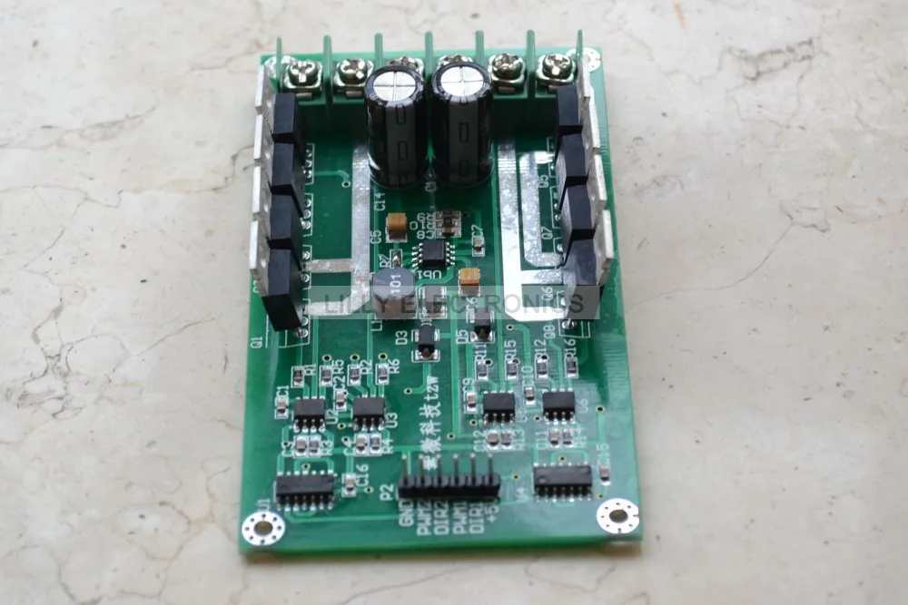
Motor and power connections
POWER connected to the positive power supply, GND power supply is negative. Two motors were connected MOTOR1, MOTOR2
Product performance parameters:
Rated voltage: 3v-36v (can be customized according to the user)
Rated Current: 10A
Peak current: 30A
Use: Freescale smart car contest Undergraduate Electronic Design Contest variety of DC motor control circuit
Dimensions: length 108mm, width 58mm
Test instructions:
1. Determine the PWM signal: this step is very important, please use oscilloscope or multimeter to sure you provide a PWM signal is accurate before test driven plate, don’t think it doesn’t matter, be sure to confirm first, the determination method is as follows, if you use an oscilloscope can see PWM waveform directly with oscilloscope, the multimeter can according to your PWM duty ratio to calculate voltage, for example, the high level state, the microcontroller port output is 5 v, PWM = 60%, we use a multimeter test the PWM output port voltage should be 5 v * 60% = 3 v,and adjust the duty ratio check should be changed. Suggest another main program starts PWM s first
2.After completing the first step, you can begin to test driven plate, first don’t answer the motor and all other signal to the POWER supply is normal,use a multimeter or oscilloscope to test waveform between the motor, for example: now I test the first way, PWM1. Dir1, + 5 v, GND, the POWER, the normal POWER GND, even have a waveform between motor1 oscilloscope for test, to see if compared with PWM1 waveform frequency, amplitude is equal to the POWER, no oscilloscope, measured With the multimeter to measure the voltage between two Motor1, and if it is equal to the POWER * PWM1, then for the next operation.
3.At the bottom of the screen to complete testing, you can be turned on the motor to do the test, but it is important to note that with the help of motor, the driver can work at 0% to 99% duty cycle of PWM modulation, the motor can get enough driving voltage, on the motor can not directly to the high level, under the condition of not hung up. More than 400 hz frequency at best
4.Finally I wish all of you have a happy shopping,If you have any need to contact me at any time. Thank you very much.
Note:If you need data sheet please cantact us!
Package:
1pc 3-36V 10A Peak 30A Dual Motor Driver Module board H-bridge DC MOSFET IRF3205